Practical Case with Siemens ET200SP PLC
By Carlos Urrestarazu
Hello, my name is Carlos Urrestarazu, and with this article, I begin a series of posts aimed at sharing real-life experiences in the field of industrial automation. Our technical office team works on a variety of projects, and one of the most recent is the implementation of CANopen communications between sensors, actuators, and a Siemens ET200SP PLC, a key solution for advanced automation environments.
This case study helps you understand how to program an efficient and secure system, taking advantage of the benefits of the CANopen fieldbus : reduced wiring, optimized costs, and a robust, security-oriented architecture. This protocol is, to a certain extent, unusual to work with, especially if never used before.
✅ Case Study: Auger Well Winch Control
The project involved designing a system of four winches capable of handling concrete rings with high precision and synchronization, ensuring safety at all times.
📦 System components
Sensors:
- 4 Redundant encoders (one per winch): provide precise position reading, allowing millimeter positioning and dynamic balance between winches (with a maximum deviation of ±30 mm).
- 4 Torque sensors: measure the individual load on each winch, ensuring that defined mechanical limits are not exceeded. Redundant for safety reasons.
- 4 Maximum unwinding limit switches: prevent the cable from excessive unwinding, automatically blocking the descent.
- 4 Maximum winding rotary switches: detect the upper limit, preventing overloads in the upward direction.
Actuators:
- Danfoss hydraulic distributor.
- 4 independently controlled winches.
Human-Machine Interface:
- HBC radio control with display, operating modes (manual, semi-automatic, automatic) and configurable settings.
- Lower emergency stop and lowering box (with UPS power).
Central control:
- Siemens ET200SP PLC.
- Radio control receiver.
🔍 Operation of the System Elements
Once we have identified the system's main components, we will move on to detailing how each one works. To do this, we will first analyze the sensors, then the actuators, and finally the human-machine interaction (HMI) elements .
🔧 Sensors
The system features critical sensors for safely monitoring and controlling winch movement. Each of the following devices is installed individually per winch (i.e. four units in total):
- Redundant encoders: these sensors provide the exact position of the cable down to the millimeter. This information is essential for achieving preset positions and maintaining balance between the four hooks, with a maximum tolerance of ±30 mm. The redundancy of these sensors guarantees compliance with safety regulations, ensuring that the system's position reference is never lost.
- Torque sensors: these measure the individual load supported by each winch, thus preventing overloads on both individual hooks and the entire winch assembly. They are also redundant devices, reinforcing system reliability.
- Maximum payout limit switches: these detect when the cable has reached its maximum extension. When this occurs, the system automatically locks the lowering valve to prevent damage or risks.
- Maximum reeling rotary switches: these detect when the cable is fully reeled in. If this condition is reached, the upward movement of the corresponding winch is blocked, protecting the system from excessive stress.
👨✈️ Human-Machine Interface (HMI)
The system is designed to provide a safe and functional interface between the operator and the machine. HMI elements include:
📡 Radio Control
The radio control allows for remote and intuitive operation of the system. Its main functions are:
- Operating modes :
- Home : complete descent to ground level.
- AutoPosition : ascend to a memorized position.
- Manual : independent control of each winch, limited only by the upper and lower limit switches.
- Semi-automatic : allows synchronized movement of all four winches via any of the joysticks (one at a time).
- Automatic : activates movements to preconfigured positions, such as:
In total, five different positions can be configured, selectable from the radio control configuration screen.
- Speed modes :
- Turtle (slow) and Rabbit (fast). The operating speed can be adjusted from the radio control interface, adapting to the needs of the environment and the operator.
- Emergency stop system :
- It includes a mushroom-shaped button that disconnects the system and stops all movements, allowing only emergency lowering.
- Monitoring system :
- The radio control display provides real-time information on the status of the limit switches, current loads, winch positions, and active alarms. The configuration menu is also accessible from this interface.
📦 Lower Safety Box
This electrical panel, located at the bottom of the system, incorporates:
- Emergency stop : immediately stops all system movements.
- Emergency lowering system : allows the load to be lowered to a safe position in case of a power outage using power from a UPS.
- Wired connection : to operate the system in case of loss of communication with the wireless radio control.
- Electrical disconnection selector : allows the machine's electrical power to be completely disconnected from the same panel.
⚙️ Additional Control Elements
- Top control panel :
- Contains the Siemens PLC and the radio control receiver .
- All electrical distribution, protection, communications and centralized control of the system are carried out from this panel.
- Electric and hydraulic reel :
- It is responsible for transferring both electrical signals and hydraulic pressure from the moving part to the fixed part of the gantry, ensuring operational continuity and stable communication during the system's movement.
🧬 CANopen – Let’s start with the Protocol.
Once we understand how the machine works, we will begin with the purpose of this article, which is how to actually program and install a CANopen system. Later, if you are interested, I can provide certain information about the HBC remote control and its programming, or about the PLC.
To start talking about CANopen, it is important to know first that it is a communication protocol based on CAN (Controller Area Network), designed for distributed automation systems, such as industrial machinery, special vehicles, medical equipment and embedded systems.
🔧 Technical definition:
CANopen is a higher-level protocol that runs on top of the physical CAN network, providing a standardized framework for:
- Communication between nodes (devices)
- Parameter settings
- Fault diagnosis
- Real-time control
📦 Key Features:
- 📚 It uses a structure called Object Dictionary, where each node has its own data table (configurations, inputs/outputs, states).
- 📡 It supports communication types such as:
- PDOs (Process Data Objects): real-time cyclical data
- SDOs (Service Data Objects): setting and reading parameters
- NMT (Network Management): node status control (start, stop, reset)
- 🧠 Ideal for master-slave or multi-master architectures
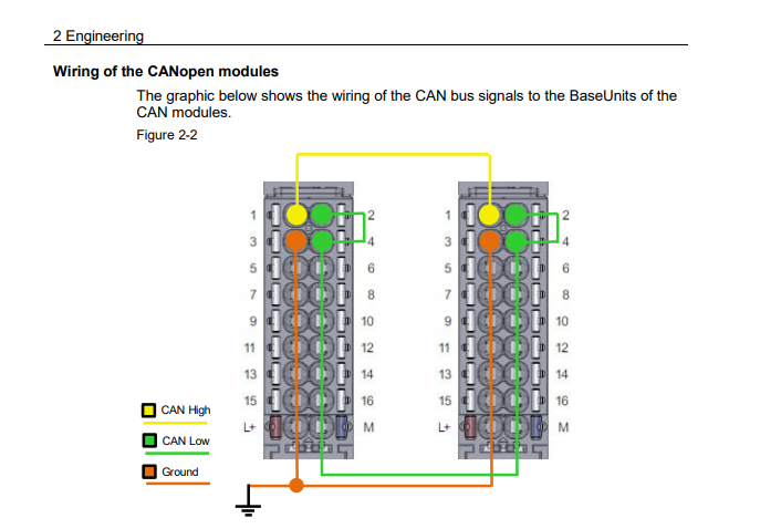
The electrical wiring of a CANopen system follows the physical rules of the CAN bus, as CANopen is based on the standard CAN network . In order to wire it correctly:
🔌 1. Recommended topology:
- Linear bus structure (The system also works in star form, as long as it is done properly).
- 120 Ω terminators at both ends.
- Derivations ≤ 30 cm.
|
Schematic Note: [120Ω]──Node──Node──Node──Node──[120Ω] |
⚙️ 2. Recommended cable:
- Shielded twisted pair cable
- 2 main lines:
- CAN_H (High)
- CAN_L (Low)
- And a third optional one: GND (common ground reference)
Example of standard cable:
- CAN_H → green color
- CAN_L → white color
- GND → black or no specific color
📏 3. Length and speed:
|
Speed (baud rate) |
Maximum bus length |
|
1 Mbps |
~40 meters |
|
500 kbps |
~100 meters |
|
250 kbps |
~250 meters |
|
125 kbps |
~500 meters |
|
50 kbps |
~1000 meters |
The lower the speed, the longer the cable length can be.
🛠️ 4. Endings:
- 120 ohms between CAN_H and CAN_L at both ends of the bus. As discussed earlier.
- Do not place more than two termination resistors.
- If you only have one master and one slave, still put terminations at each end.
✅ Summary of connections by device:
Each node must have:
- CAN_H
- CAN_L
- GND (optional, but highly recommended)
- Power supply (usually 24VDC, depending on the device)
🧩 CANopen System Architecture
Below is the table with the nodes and their respective Node IDs :
|
Device |
Node ID |
|
Encoder Cab1 |
55, 56 |
|
Encoder Cab2 |
65, 66 |
|
Encoder Cab3 |
58, 59 |
|
Encoder Cab4 |
68, 69 |
|
Hydraulic distributor |
80 – 85 |
|
Radio control |
1 |
|
PLC (CM Can - Manager) |
40 |
|
Note: A second CM Can card in the PLC works in “Transparent” mode , so it does not appear as a visible node on the network. |
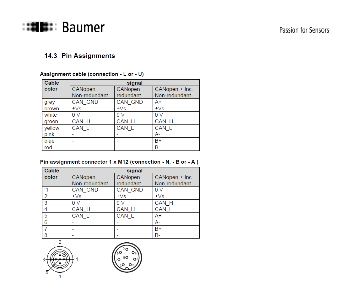
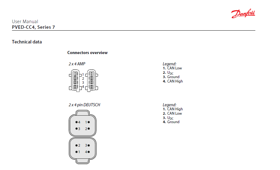
📐 Wiring Diagrams (by manufacturer)
Technical diagrams provided by manufacturers.
- Baumer Encoder
- Danfoss Distributor
- HBC radio control
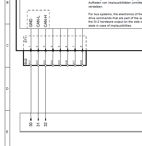
- Siemens CM Can Modules
By making the complete electrical connection diagram between all the devices we would achieve something similar to the following:
🌐 CANopen Network Distribution
 CANopen network distribution
This distribution is very important because it is through these nodes that we will communicate with the devices.
🖥️ System programming from the PLC.
Introduction
We will now focus on PLC programming. Although we will primarily address this aspect, we will also discuss key configuration aspects for sensors and actuators.
Once parameters such as Baud Rate, Node ID and the PDO structure have been defined, we can now establish the communication logic in the PLC.
🧭 Configuration per device
🔧 Baumer Encoder
- Requires CAN interface compatible with Baumer Sensor Suite.
- The following are configured: Node ID, Node ID Redundant and PDOs.
- The manufacturer provides the EDS file, which facilitates automatic integration into the system. Only the NodeID and a few parameters in the PDO need to be modified.
🔧 Danfoss Distributor
- It only allows modifying Node ID.
- It has no preconfigured PDOs: communication must be done through manual messages.
|
Example of ID change (from 80 to 81): |
|
$001CEF80C8 X $8 $F9 $20 $09 $00 $01 $00 $09 $50 $001CEF80C8 X $8 $F9 $61 $73 $73 $77 $6F $72 $64 $001CEF80C8 X $8 $F9 $31 $97 $FF $FF $FF $FF $FF $001CEF80C8 X $8 $F9 $20 $0B $00 $33 $00 $02 $81 $001CEF80C8 X $8 $F9 $00 $00 $00 $00 $00 $00 $00 |
It can be done from Danfoss software or a CAN sniffer.
Commands for valve position control will be discussed later.
📡 HBC Radio Remote Control
- Device configured from factory
- Delivered with Node ID (e.g. 1) and EDS file for direct integration
At this point we have configured the peripheries, and can move on to the PLC.
⚙️ PLC configuration on CANopen networks
Integration of CM CAN Transparent and CAN Manager cards in TIA Portal
In this section, we start with a previously configured project (security, logic, and general structure). If you need more in-depth details about the basic architecture, we will expand on that in future installments.
The central control equipment is a Siemens ET200SP safety unit, with digital and analog input/output modules and two CM CANopen communication cards .
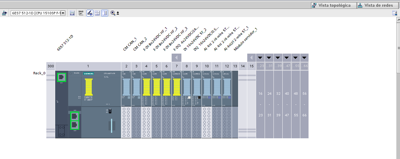
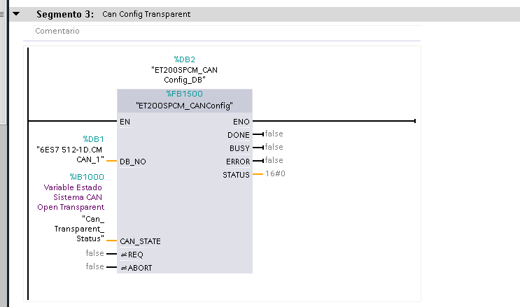
🧩 CM CAN_1 Card – CAN Transparent Mode
This card is used to communicate with the Danfoss hydraulic distributor, which does not have EDS, so it requires programming through manual messages.
|
🔧 Configuration:
|
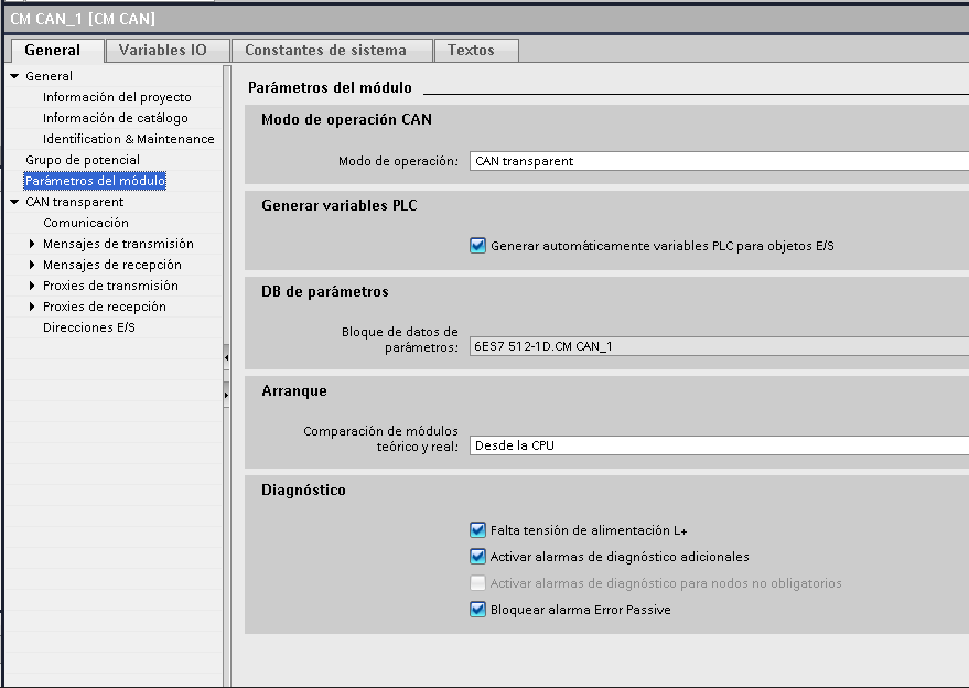 |
The following sections are enabled when performing the above configuration:
- Communication: General bus settings
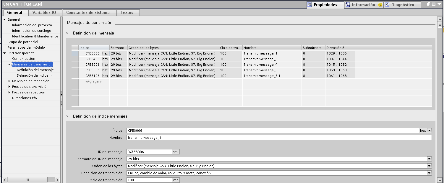
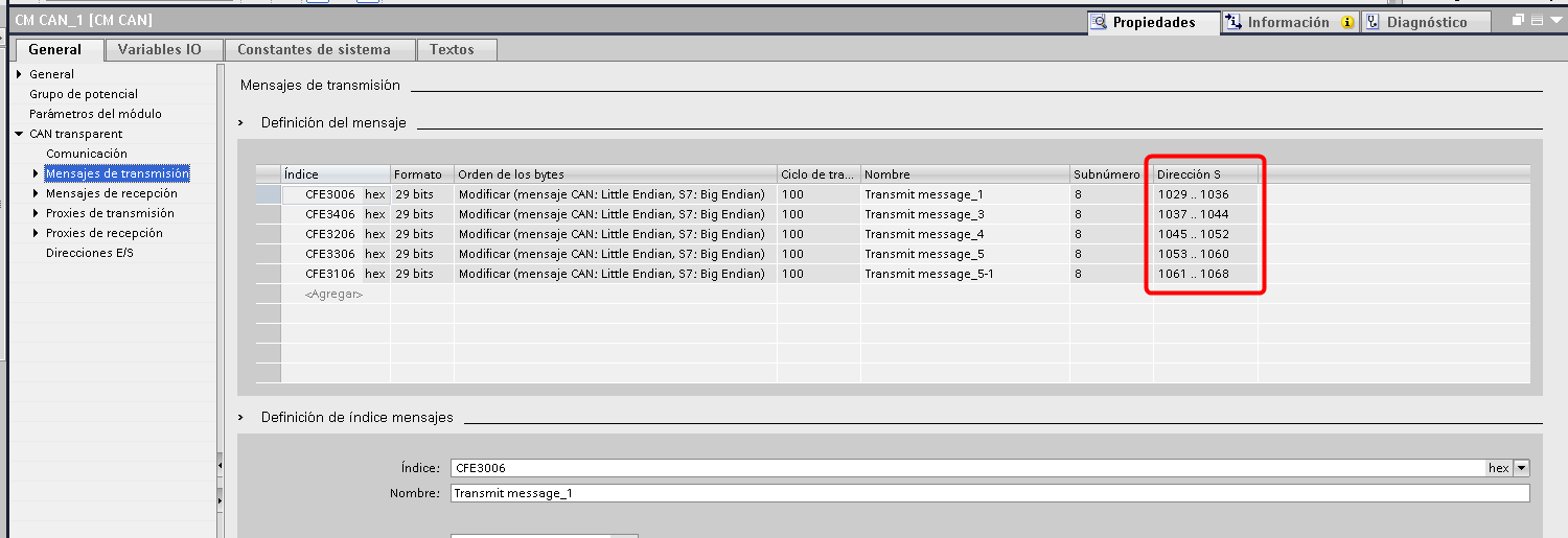
- Broadcast messages: commands to operate the valves
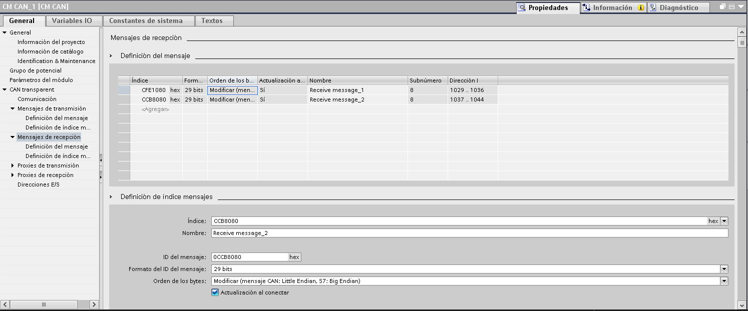
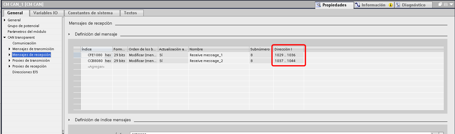
- Reception messages: reading errors, position and status
- Proxies: not used in this case
In Transparent mode , the module does not appear as a node on the network , acting as an “invisible spy”.
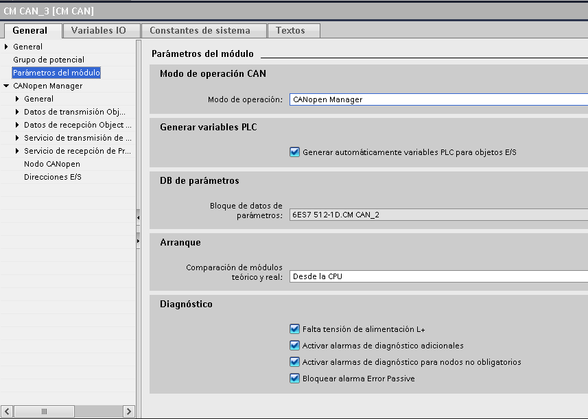
📡 CM CAN_2 Card – CAN Manager Mode
This second card connects to the encoders and the HBC radio control , allowing the use of the manufacturer's EDS files and integration by PDOs.
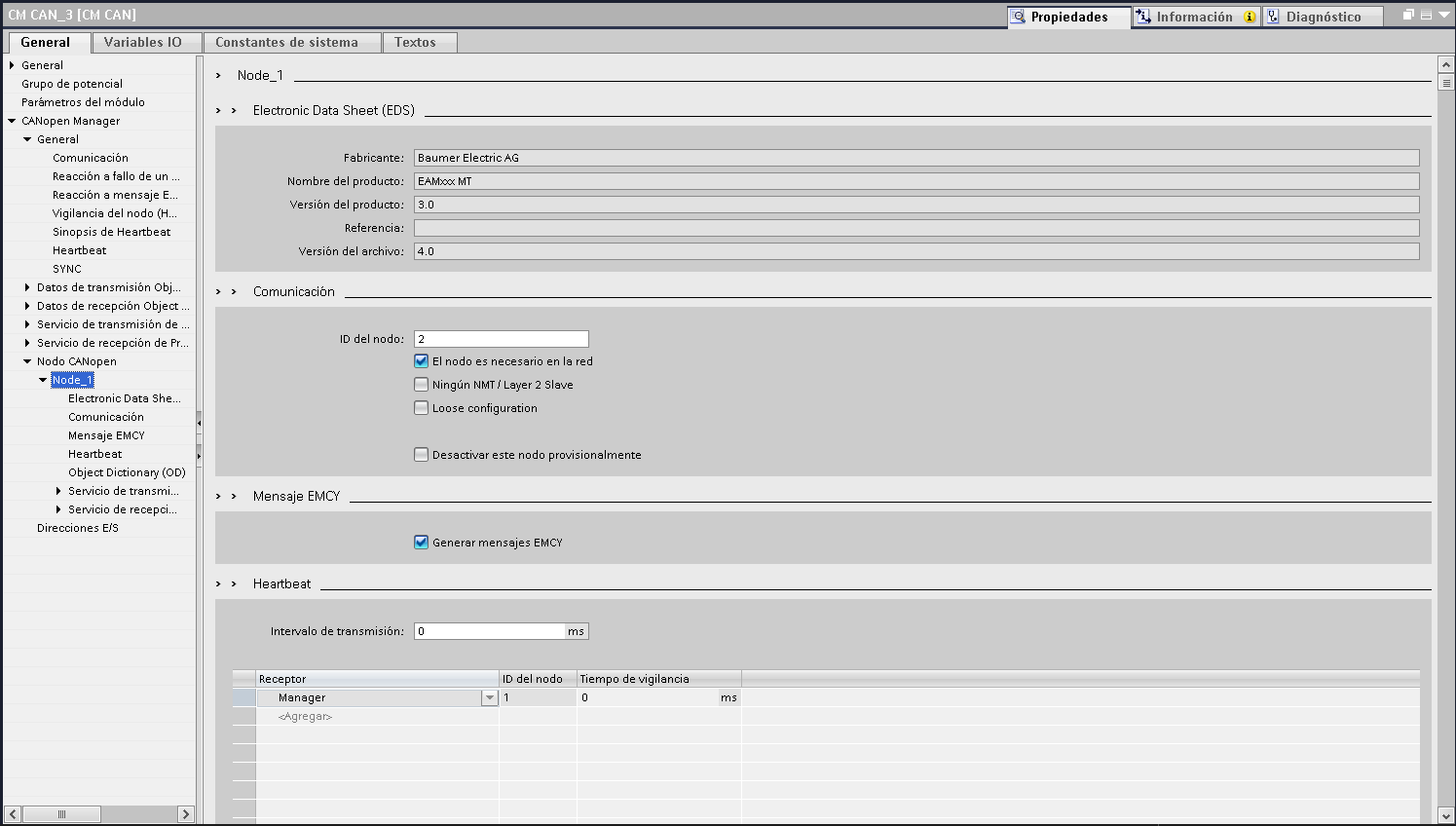
⚙️ Configuration:
|
 |
📥 EDS node integration
- In the CANopen Node section , double-click <Add>
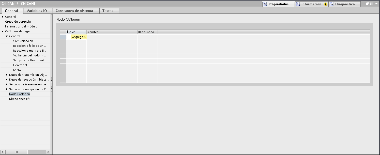
- Import the EDS file provided by the manufacturer
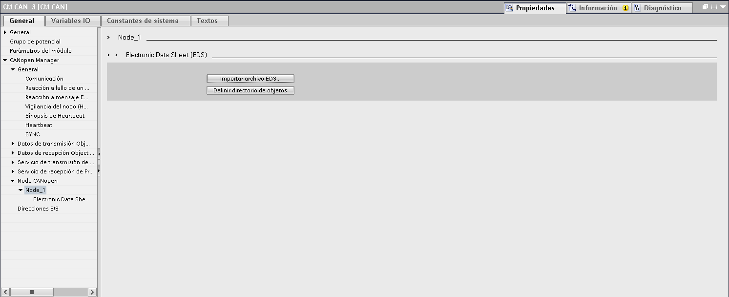
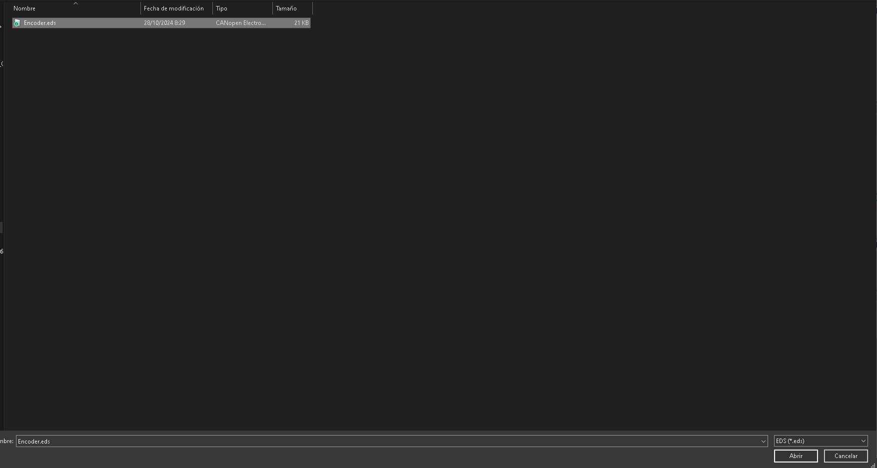
- Rename each node to identify which device it belongs to
- Configure the values previously loaded with the supplier's software
Since the encoders are redundant, you will need two nodes per winch.
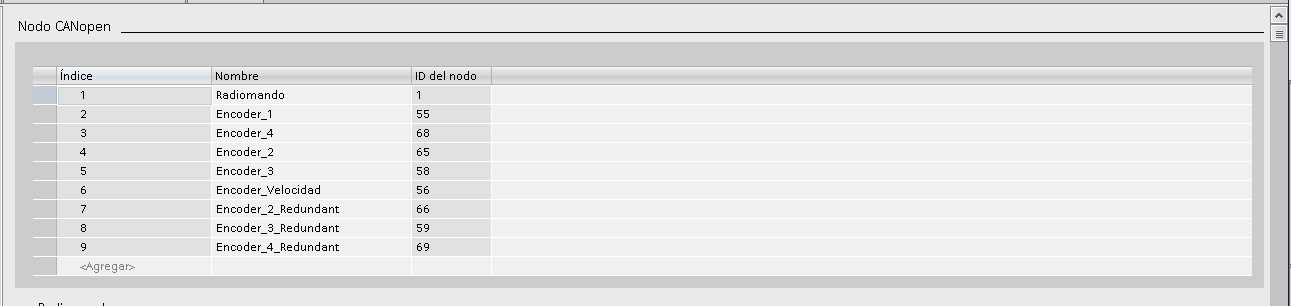
Summary of all configured nodes.
🔄 PDO Configuration
For each node, the PDOs you want to use must be activated and configured.
- PDO Streaming Service: Reading data from sensors
- PDO Reception Service: writing data from the PLC
🧠 Tip: Think from the device's perspective. Is it sending or receiving ?
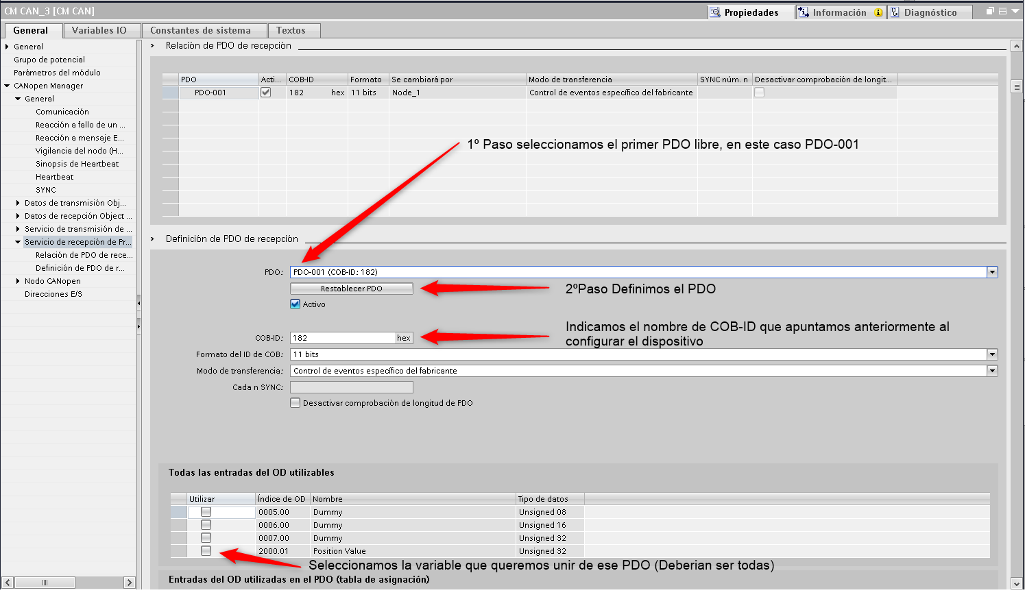
📌 Practical example: configuring reception from an encoder
- Activate PDO on the device
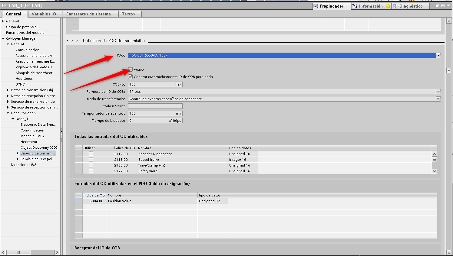
- Write down the COB-ID (Our case 182)
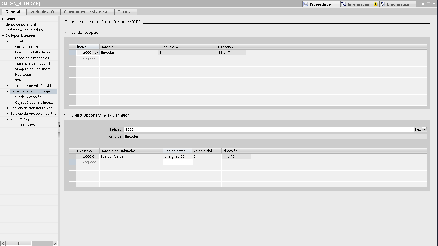
- Go to PDO Reception Data
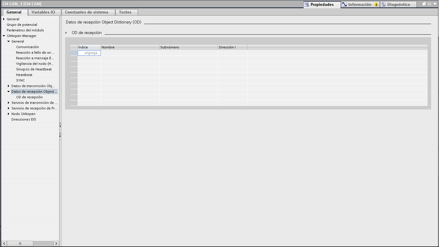
- Click <Add> and rename the object
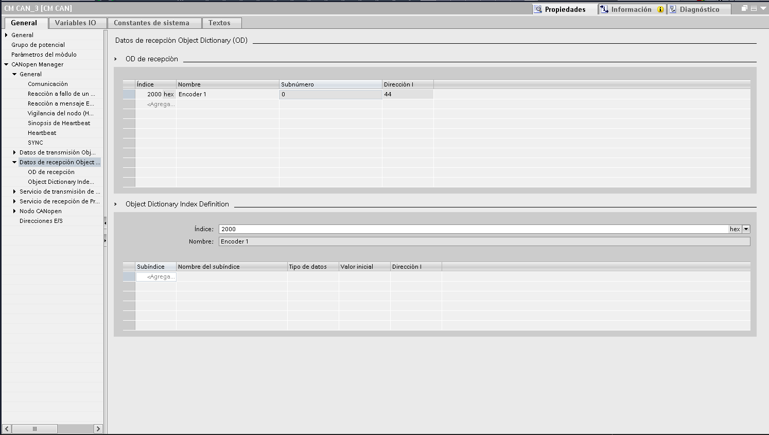
- Add sensor variables
- Go to PDO Reception Service
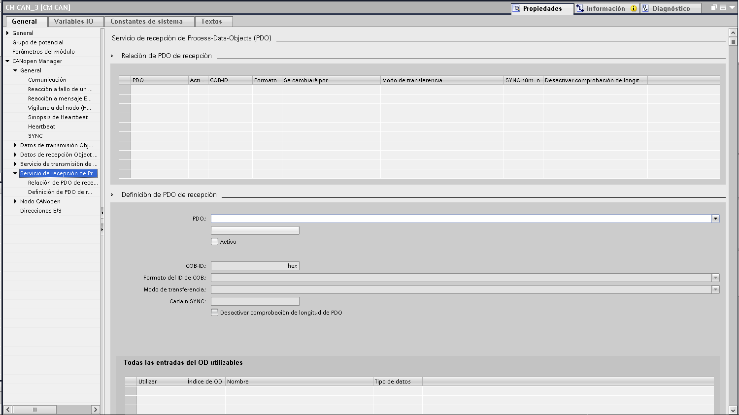
- Create a new PDO and link it to the COB-ID (Our case 182)
This process is repeated for each device and exchange address.
▶️ Execution and activation in program cycle
CM card CAN_1 (Transparent)
- To activate: write 1 to address QB1000
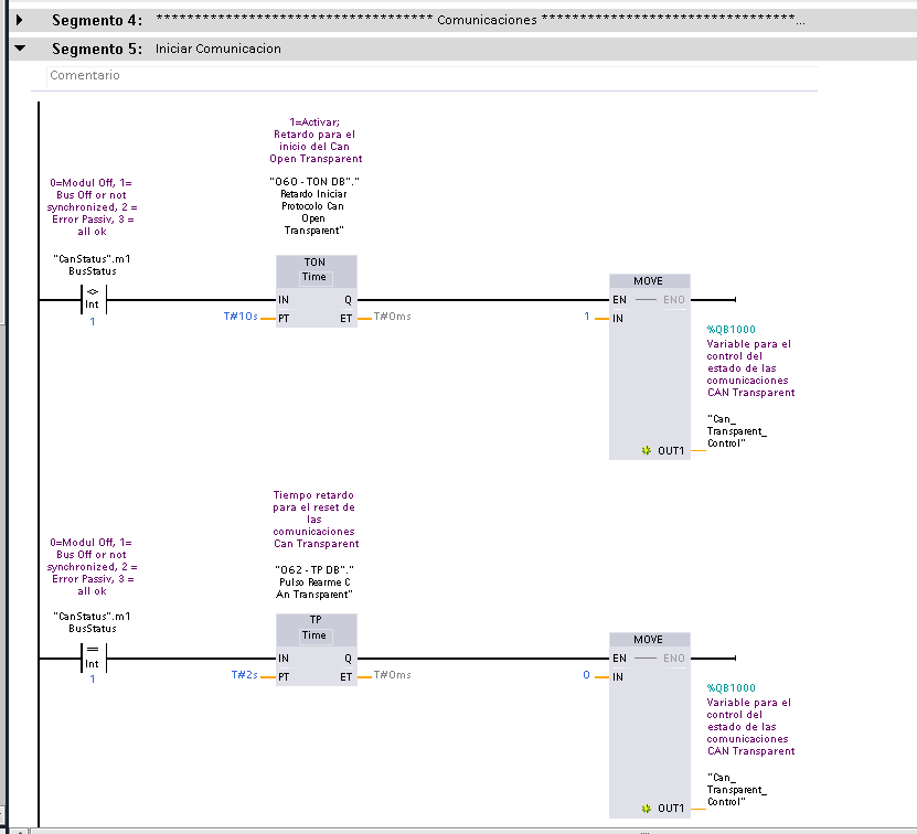
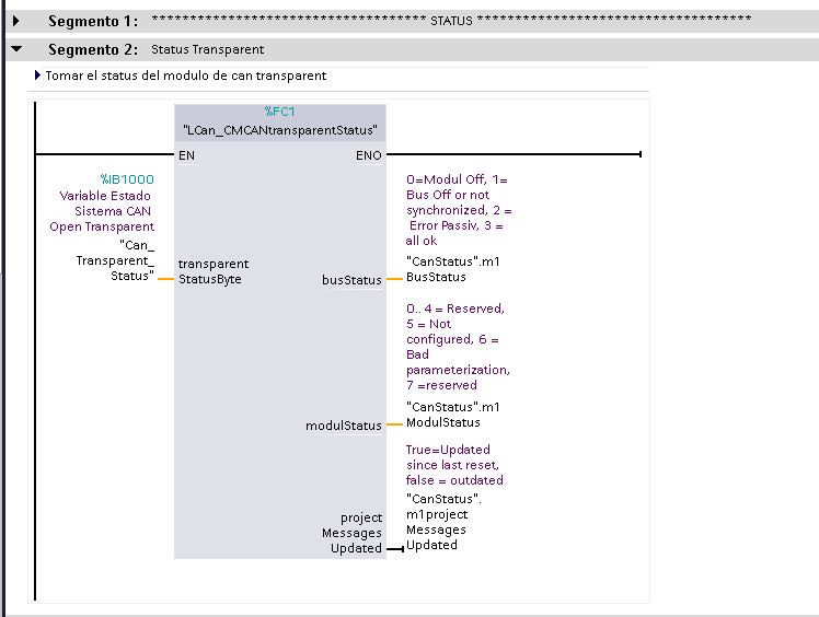
- Card status via status byte:
- 0 = Module disconnected
- 1 = Bus Off / not synchronized
- 2 = Passive error
- 3 = All correct
- Where to locate entrances and exits addresses
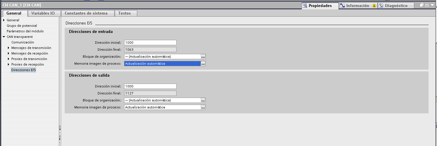
- Outputs
- Inputs
CM CAN_2 Card (Manager)
- Activation: write 16#05 (hex) to QB94
Associated inputs and outputs can be viewed in the project's I/O configuration as well as on the transparent CAN card.
🚨 Not communicating? Diagnostic tools
Do not worry! If you are still unable to communicate after setting everything up, you have other potential resources.
This is where the use of a CAN sniffer comes in, essential for debugging problems in industrial networks.
🧪 Recommended tools:
- HD67316-U-D1 – CAN Analyzer
adfweb.com/products/CAN_BUS_analyzers.asp
✔️ Professional accuracy, high reliability - USB to CAN Adapter STM32 (Waveshare)
waveshare.com/product/usb-can-a.htm
✔️ Economical and versatile
🛠️ How to use the CAN Analyzer?
|
 |
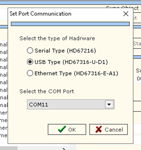
Key steps:
- Check the COM port in Device Manager
- In the software, go to: Function > Set Port
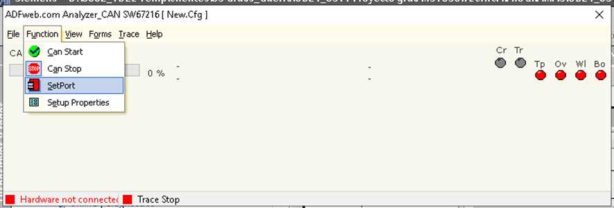
- Set the correct COM port
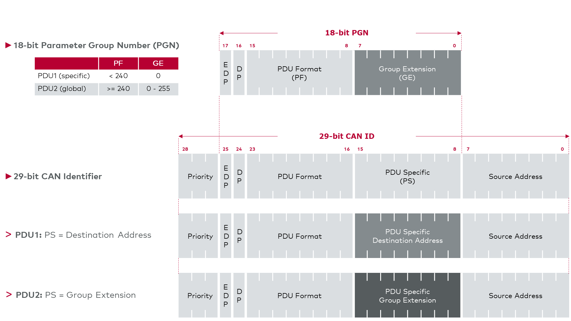
🧾 Standard or Extended? CAN Identifiers and Common Mistakes
CAN communication can operate in two identifier formats:
- Standard (11 bits)
- Extended (29-bit)
In the TIA Portal, this setting is made in the node or message configuration section, under the "Message ID Format" option . This value defines the length of the identifier to be used in CAN telegrams.
⚠️ If you configure the system in one format and the sniffer in another, you will not see any traffic, even if it actually exists. This is one of the most common and frustrating mistakes when debugging a CANopen network.
That is why it is essential that the sniffer is configured with the same format (Standard or Extended) you are using in the project. Otherwise, you will think there is "no communication," when you are simply not reading the correct format.
🛠️ How to configure your CAN Sniffer to work in Standard or Extended mode
⚙️ Step 1: Select the identification mode (Standard or Extended)
- Go to Function > Setup Properties .
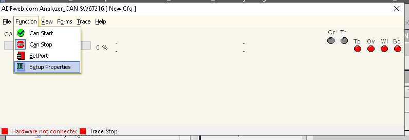
- Locate the “Protocol” parameter .
- Choose between:
- Standard (11-bit Identifier)
- Extended (29-bit Identifier)
|
🧠 Tip: If you do not know which one you are using, check it in your PLC software (TIA Portal). For each node or message, you can see whether an 11-bit or 29-bit ID is being used. |
📶 Step 2: Set the speed (Baudrate)
On the same configuration screen:
- Set the baud rate to the same as your CANopen network.
- Typical example: 250000 or 125000 bps (Our case 250kbit/s)
▶️ Step 3: Start listening
- Click Start or Begin Sniffing .
- You will see CAN traffic appear in real time if everything is configured correctly.
If you do not see anything: Check the ID mode, speed, and power connections. Also, verify that the network is active.
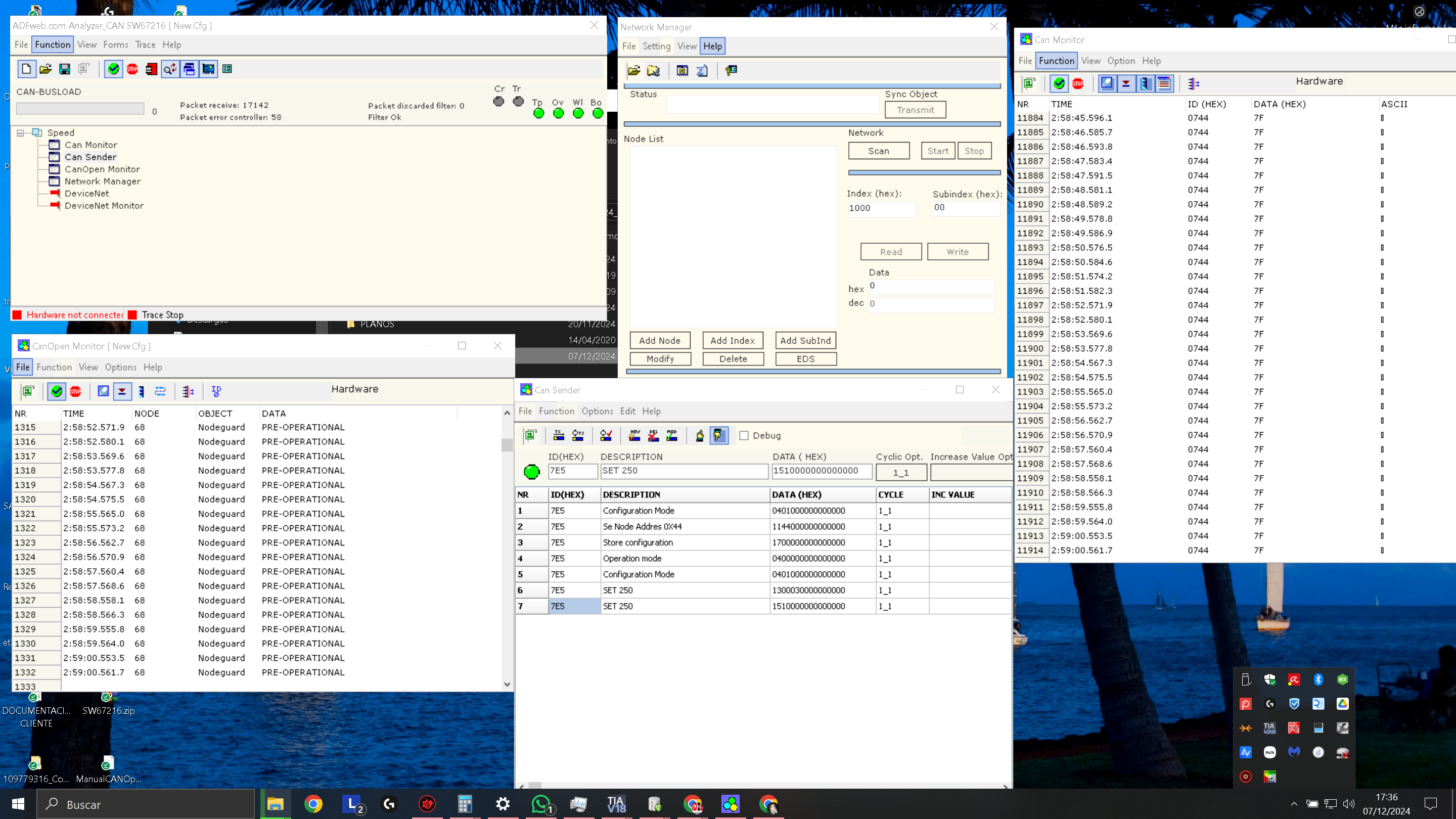
|
🧠 Tip: Remember that in the “Forms” section you can open different windows, where you can view the communication in various formats. |
🧠 Conclusion
This article does not only aim exclusively to introduce the CANopen protocol from a technical perspective, but also to show how it integrates into real-world industrial automation systems. Using this protocol has allowed us to implement a robust, efficient, and secure system under demanding conditions, optimizing both installation and maintenance time.
Are you interested in the next article focusing on programming the HBC remote control or advanced use of the Siemens ET200SP PLC on CANopen networks?
What do you want to see in the next article?
📡 Advanced programming of the HBC radio remote control
🔧 Error management and network monitoring in industrial CANopen
🧠 Other interests
Links of Interest:
|
Example Tia Portal |
Tia Portal Example (Hardware) |
Sensors Documentation |

Publication Date: 06/25/2025